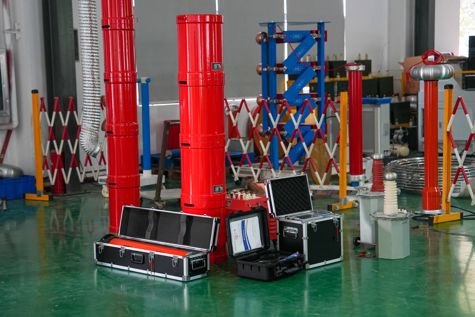
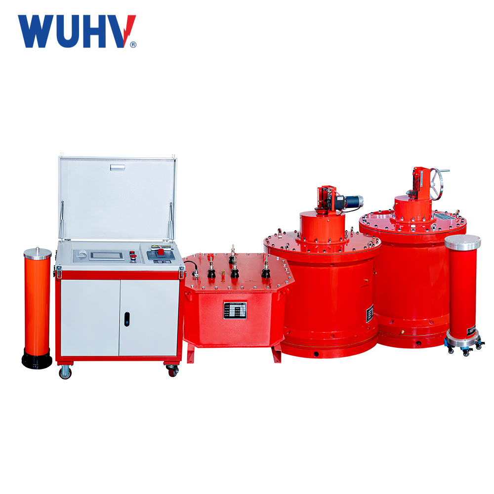
The series resonance under UHV power can help many power workers conduct various power tests more conveniently.
1、 Preface
With the rapid development of the economy, the demand for green energy such as electricity is also expanding rapidly. Land resources are becoming increasingly scarce and the demand for electricity is increasing. Power cables are becoming more and more long, transformer voltage levels are increasing, and capacities are growing. GIS equipment is also widely used, and on-site AC withstand voltage is becoming more and more popular in power equipment. Series resonant equipment, with its characteristics of small size, high voltage, and lightweight installation, is becoming increasingly widely used. This article analyzes several problems encountered in the testing of series resonance equipment and proposes solutions.
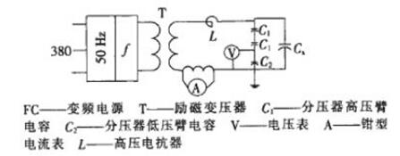
2、 On site series resonant withstand voltage equipment test wiring diagram

Wiring diagram for frequency conversion resonance test
In the figure: FC variable frequency power supply T excitation transformer L reactor C voltage divider
3、 Power capacity
(1) Experimental phenomenon
During the AC withstand voltage test on the high-voltage side of the main transformer at a 220kV substation, the power supply tripped and the variable frequency operation box displayed low power supply voltage. The estimated experimental parameters are as follows
Factory capacitance (pF), reactor arrangement frequency calculation value f (Hz), current calculation value IL (A)
Note: 1. Each section of reactor Ue=37kV, Ie=1.16A,L=100H, There are a total of 6 sections. Voltage divider Ue=200kV, C=1000pF。
(2) Problem analysis
During the experiment, the required test voltage for the set is 160kV, and the test frequency and reactor voltage level meet the test requirements. When the voltage rises to 150kV, the frequency conversion operation box displays a duty cycle of 85%, and the power supply voltage trips due to low voltage. Due to the normal boost capability of its entire system, the main reason is due to issues with the variable frequency operation box or power supply side. From the above data, it can be seen that the entire variable frequency power supply is close to full load, and the power supply voltage is low. Therefore, the trip is caused by the equipment tripping at full load due to low power supply voltage. Further inspection of the power supply revealed that the voltage of the temporary power supply box was only 200V when it was unloaded, far below 220V. During the boost process, the voltage decreased due to load reasons, resulting in the power supply being fully loaded and the duty cycle being too high, causing the variable frequency power supply to.
(3) Problem solving
Based on the above reasons, the power supply was ultimately replaced and the power cable was thickened to reduce the line voltage drop. The entire system worked normally, and the voltage measured at the instrument end was 200V. When the test voltage was reached, the duty cycle was 71%
4、 Poor wiring contact
(1) Experimental phenomenon
Phenomenon 1: The on-site resonance point cannot be elevated, and the instrument cannot perform self resonance.
Phenomenon 2: The on-site resonance system has normal air lift, but after connecting the load, the resonance point cannot be found and the voltage cannot rise, and discharge sound can be heard.
Phenomenon 3: The on-site resonance system has normal air lift, but after connecting the load, the resonance point cannot be found, the voltage cannot rise, and the discharge sound cannot be heard.
(2) Cause analysis
Phenomenon 1: Unable to find, it may also be caused by internal disconnection of the test line. Due to the need for a safe distance between the excitation transformer and the operation box, the connection between them is prone to pulling and causing the solder to fall off. This is manifested as the excitation transformer having no output voltage. When troubleshooting, use a multimeter to check this section of the line. However, if it is removed without pulling, the solder joint may touch, causing the illusion that the line is intact.
Phenomenon 2: Possible cause is the disconnection between the resonant system and the test sample. When the high-voltage lead between the test sample and the resonant system is disconnected, due to the small distance and low voltage, breakdown occurs and a sound is heard. However, due to the previous incorrect search for the resonant point, even if the gap is broken down, it cannot conduct normally, thus unable to resonate.
Phenomenon 3: Of course, due to the unreliable grounding of the test sample, the capacitance changes, which can also cause the resonance point to move and become unstable. This problem is more common in high-voltage cable withstand voltage when the outer sheath protector is not grounded.
(3) Problem solving
When using series resonance testing equipment, it is important to ensure reliable wiring and correct instrument wiring.
5、 Reactor issue
(1) Experimental phenomenon
Phenomenon 1: The on-site resonance system has normal air lift, but after connecting the load, the resonance point cannot be found, the voltage cannot rise, and the discharge sound cannot be heard.
Phenomenon 2: The on-site resonance system has abnormal air lift.
(2) Cause analysis
Phenomenon 1: Due to the system's vibration frequency being set to 30-300Hz and the system's self resonant frequency being 200Hz, connecting the test sample will result in a decrease in the resonant frequency. However, some test samples have a large capacitance, causing the resonant point to be outside the tuning range of the operation box (below 30Hz), which is particularly common in 10kV cables (with longer cables).
Phenomenon 2: Adopting a step-by-step substitution method to identify the damaged reactor. If conditions permit, specialized inductance measuring instruments can be used to test the inductance of the reactor to see if it is at its rated value.
(3) Problem solving
Phenomenon 1: At this point, the capacitance of the test sample should be calculated in advance, and parallel compensation with reactors can be used to reduce the amount of electricity in the test sample without increasing the total circuit current.
Phenomenon 2: Replace the reactor.
6、 Variable frequency power supply issue
(1) Experimental phenomenon
Phenomenon 1: The system keeps restarting.
Phenomenon 2: After the power supply is boosted, it suddenly trips and cannot be boosted normally.
(2) Problem solving
Phenomenon 1: The problem is caused by loose internal components of the system, but the specific loose components are unknown. The on-site method is to replace the variable frequency power supply.
Phenomenon 2: This problem is caused by the breakdown of the transistor protection component of the variable frequency power supply. It needs to be returned to the factory for maintenance or replaced with the corresponding protective component on site.
7、 Conclusion
Due to the complexity of on-site testing, the above-mentioned problems often occur in on-site equipment. It is necessary to analyze them one by one based on different phenomena, and it is absolutely forbidden to blindly apply pressure, which may cause equipment damage.


