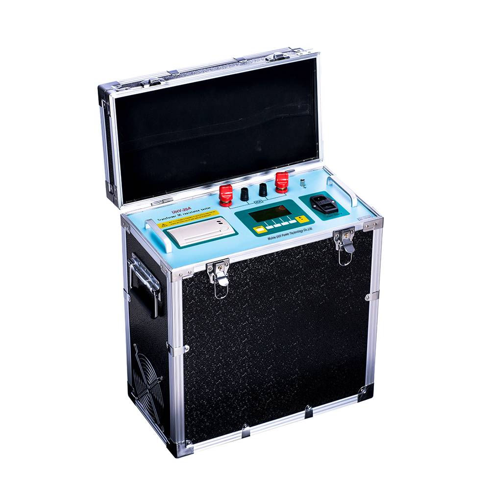
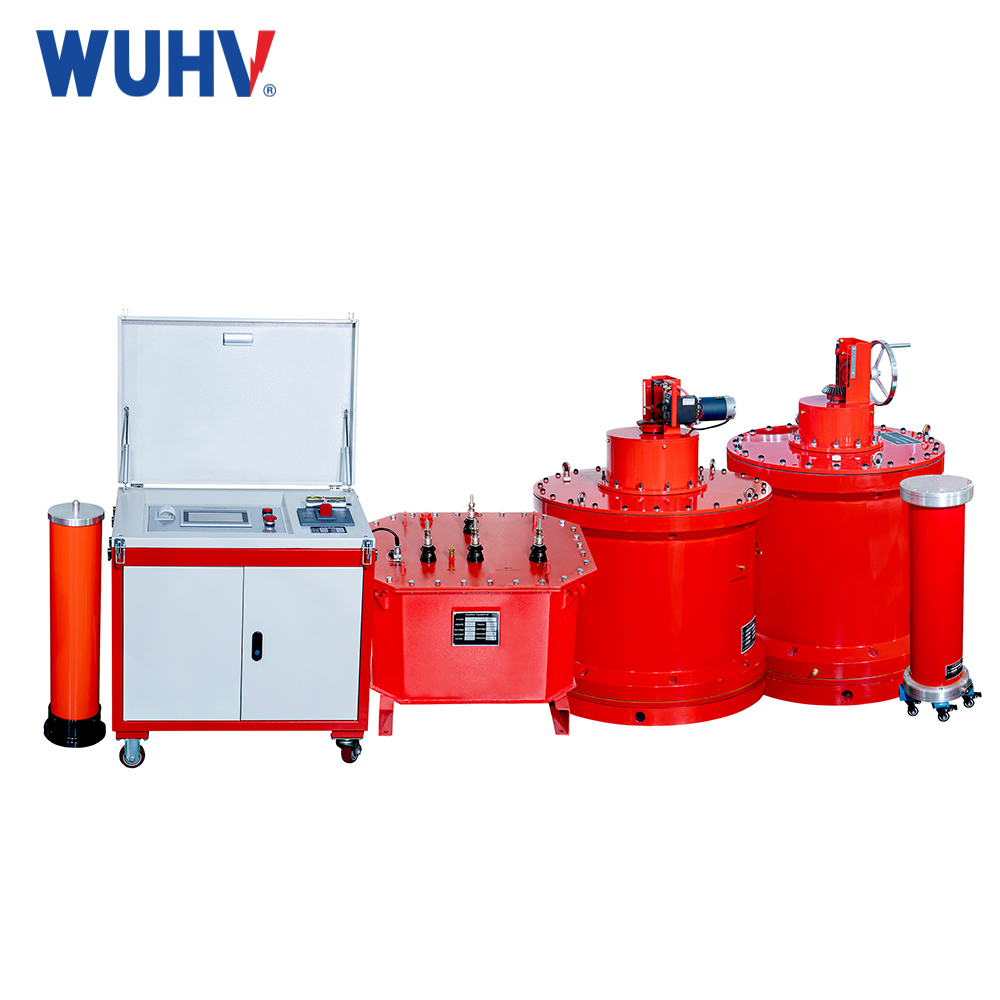
A DC Winding Resistance Test is a fundamental electrical measurement used to determine the ohmic resistance of windings in devices like transformers, motors, generators, and reactors. Performed with direct current (DC), it eliminates inductive effects, providing precise resistance values for quality control, diagnostics, and performance validation.
Purpose
1.Baseline Data: Establish reference resistance for future comparisons.
2.Fault Detection: Identify issues like loose connections, broken conductors, or uneven winding turns.
3.Loss Calculation: Compute copper (I²R) losses for efficiency analysis.
4.Temperature Validation: Verify winding temperature rise during heat runs.
Test Equipment
Primary Tools:
Micro-ohmmeter (4-wire Kelvin method, accuracy ±0.1%).
DC resistance bridge (Wheatstone/Kelvin bridge for high precision).
Alternatives:
Voltmeter-ammeter method (less accurate, requires stable current source).
Accessories:
Temperature sensor (infrared gun or RTD), current clamps, heavy-duty leads.
Procedure
1.Safety & Prep:
De-energize equipment, ground windings, and discharge capacitance (critical for transformers).
Record ambient/winding temperature.
2.Connection:
Use 4-wire Kelvin setup: Separate current injection (C1, C2) and voltage sensing (P1, P2) probes.
Ensure tight, clean contacts (sand terminals if oxidized).
3.Stabilization:
Apply DC current (typically 10–30% of rated current).
Wait for resistance/current to stabilize (1–10 mins, varies with inductance).
4.Measurement:
Record resistance once stable (auto-average multiple readings if possible).
5.Temperature Correction:
Convert to standard 20°C:
R20=Rt /【1+α(t−20)】
Rt: Measured resistance at temperature t (°C)
α: Conductor temp. coefficient (Copper: 0.00393/°C, Aluminum: 0.00403/°C)
Key Considerations
Current Selection:
High enough for signal-to-noise ratio but avoid overheating.
Transformers: Follow IEEE C57.12.90 (e.g., 1–20A based on rating).
Demagnetization:
For inductive devices (e.g., transformers), demagnetize post-test to prevent residual DC flux.
Winding Connections:
Measure per phase (isolate other windings).
For delta windings: Measure line-line and calculate phase resistance.


